5.0
1 review
Everyone
Content rating
0
Downloads


PICFTDI (USB Communication) description
PIC32 hardwired communication using an OTG USB cable to connect directly to your microcontroller. Note that no extra shield or code libraries are required. All you need to use is Serial.begin(9600).This simple-to-use app features:
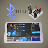
★ 24 buttons to control your microcontroller with a press of the button (see Photo #1)
★ Ability to send/receive data to/from the PIC32 MCU via chat-like terminal view layout (see Photo #2)
★ To change the string, simply long-press any of the buttons (see Photo #3) or use the chat like terminal view to type any string you would like.
★ App auto-launches when PIC32-based boards are connected
On the PIC32 microcontroller use:
Serial.begin(9600);
To read data on the microcontroller sent from the Android device use:
Serial.read();
To send data from the microcontroller to the Android device use:
Serial.println();
See the code example below or visit my website to download more example code files. Depending on the phone or tablet you may have to scroll down to access all 24 buttons.
This will only work with PIC32 boards that have an FTDI_USB-to-serial chip. My other app called “PIC32USB” supports PIC32 boards that have a direct USB connection to the D+ and D- pins on the microcontroller with no other chip in between.
// Microcontroller code example
String inputString ="";
char incoming = 0;
void setup ()
{
delay(15);
Serial.begin(9600);
delay(50);
pinMode(PIN_LED1, OUTPUT);
digitalWrite(PIN_LED1,LOW);
//Add pinMode for LEDs here, etc
}
void loop ()
{
if(Serial.available()>0)
{
while(Serial.available()>0)
{
incoming = Serial.read();
delay(4);
inputString += String(incoming);
}
//must be exact spelling, no extra spaces
if(inputString == "LED on")
{
digitalWrite(PIN_LED1,HIGH);
delayMicroseconds(1);
Serial.println("LED is now on");
//add code here
}
if(inputString == "LED off")
{
digitalWrite(PIN_LED1,LOW);
delayMicroseconds(1);
Serial.println("LED is now off");
//add code here
}
}
inputString ="";
delay(50);
}
Please note: Due to the hardwired connection to the phone or tablet, this application is use at your own risk. It is recommended to use an OTG USB cable that allows an external power source if you are drawing more than 200mA of current from the device. Be careful to never create a short from power to ground since you have the potential of damaging your USB connection on your device. I have extensively tested this with most of the available PIC32 microcontrollers that have a FTDI_USB-to-serial chip. If using an OTG USB cable that allows an external power source it is recommended to only use the factory charger that came with the phone or tablet as the external power source.
This application defaults to a baud rate of 9600, but you have the option to choose from a variety of other baud rates. Using the settings menu option while on the terminal view layout you can select up to a 921600 baud rate. Note that depending on your microcontroller some speeds may not be recommended.
Thank you for checking out this application. See my website below for more details.